|
|
|
|
|
|
Noctis' Engine-Sword
Gruelling Cosplay Project 2010
Author's
Comments:
Herein lies the account of the biggest project of my life (as of June 2010). I am a horrible procrastinator and I am proud to say that I never, ever approached anything in my life with such fervent, consistent, and persistent passion as I have with this project. Best of all, I completed it in time. Barely so, however; as the paint was still tacky on the first day of the convention. While I put so much blood and sweat into this project, the reality of finishing this work still feels as a miracle to me. It is a tremendous undertaking and I caution you against making this prop.
It is my hope that this web account will allow others to avoid some of the pain and hassle, when and if, they should approach a project of such magnitude on their own accord. The chances are slim; as I'm sure that the character design for Final Fantasy Versus XIII will be invariably different in a few years or within the decade (^_^); when the game comes to be released.
I set out to make the most accurate prop possible given the poor references that I had available to me (as of this time). I believe that I largely succeeded.
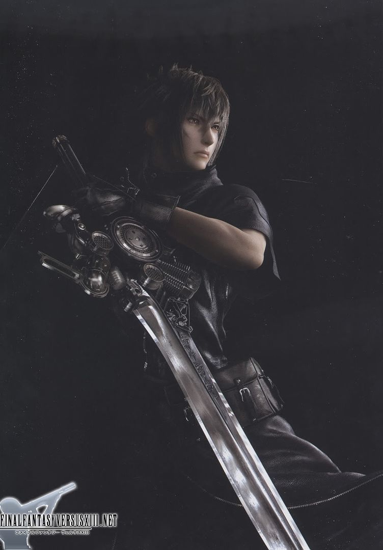
There are a plethora of weapons for Noctis, but I decided to go with the ugly-as-ass main sword as references were easy to find. Ironically, it was (likely) the most difficult project. For the record, I decided to cosplay him as I love his overall look, but I honest-to-God hate his weapon. It reflects the continuing trend in recent Final Fantasy games to have fantastical, ugly, and impractical looking weapons.
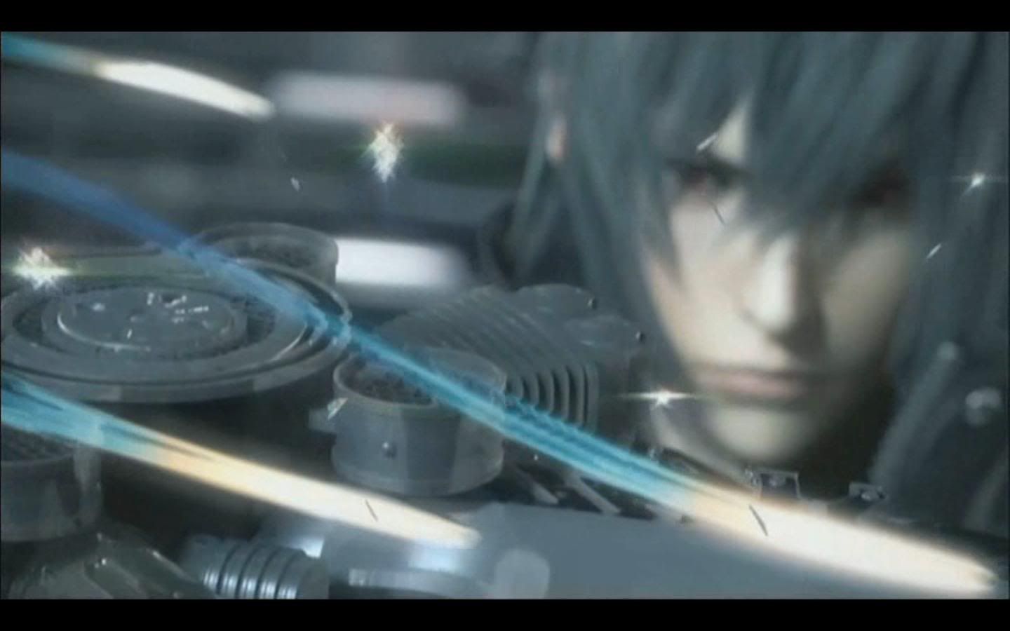
Anyway, for your reference here are the images that I used as references for this project. Some of them are screenshots from the digital movies.
|
|
|
|
|
|
I absolutely have no ownership of the images above, nor did do I possess the skills to do anything fancy with them. I also want to make it known that I absolutely do not recommend that you make this prop. But if you want to know --- keep reading.
Supplies |
Tools |
|
|
|
|
|
|
|
|
|
|
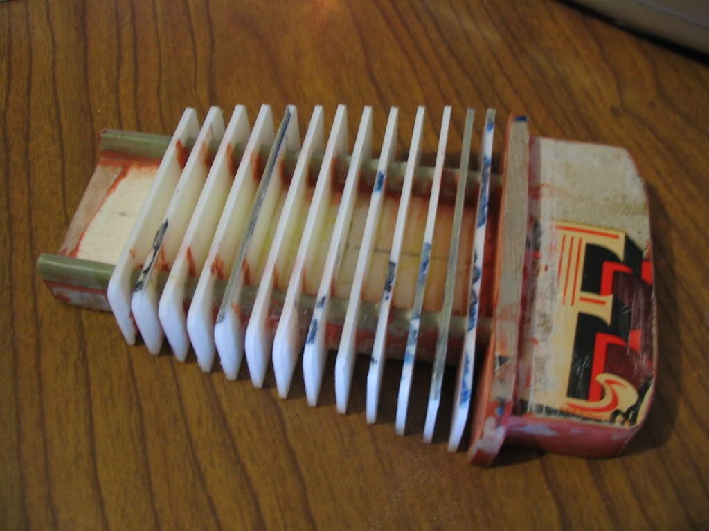
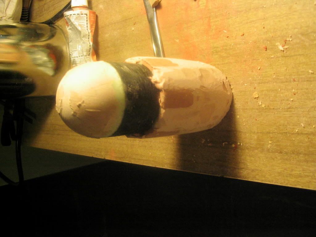
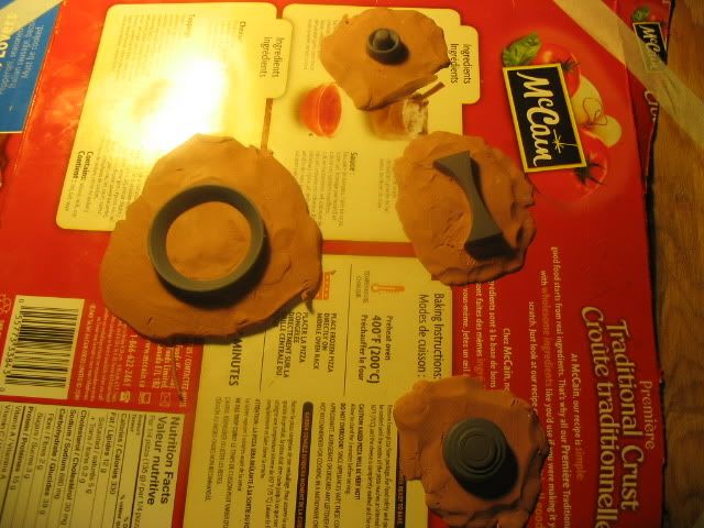
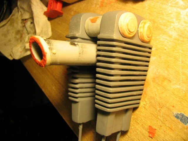
My first attempt was a failure.
I tried to make the main blade out of foam, and it was inadequately covered with low-tack masking tape. When the resin went on, it flexed, bent and died. After many weeks of failed attempts at patching it up, I finally gave up when my completed engine (last two images) melted during the mold making process.
The face plate was meant to be cast and duped. I ended up using the same plate and made a second copy manually – it was much easier than making a mold and casting an imperfect part.
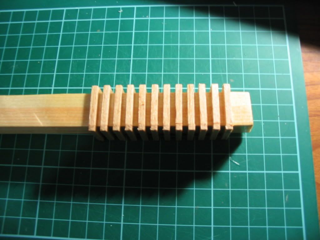
The wooden beam there was to be the inner part of what I call the S-Block. I took a guess as to the shape and detail of what it looked like. I think that I was much more spot-on this year.
After a crushing defeat, I went back to my project nearly two years later.
|
|
|
|
|
|
|
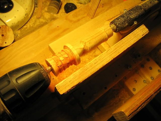
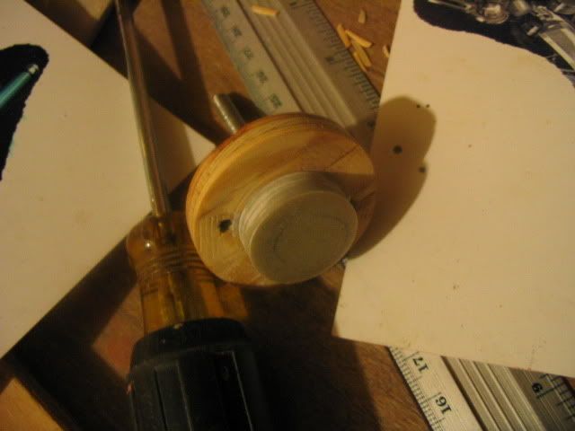
The “lathe” is a very ghetto (but fully functional!) attempt at the fine-tuned machine that one can purchase. However, with some scrap wood and a new $22 drill, one was made with a sliding tail-stock that was perfectly adequate (with some hand-holding) at turning the parts that I needed for this project. I do not believe that I could have done this without the help of my 'lathe'.
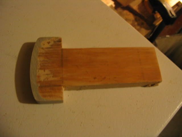
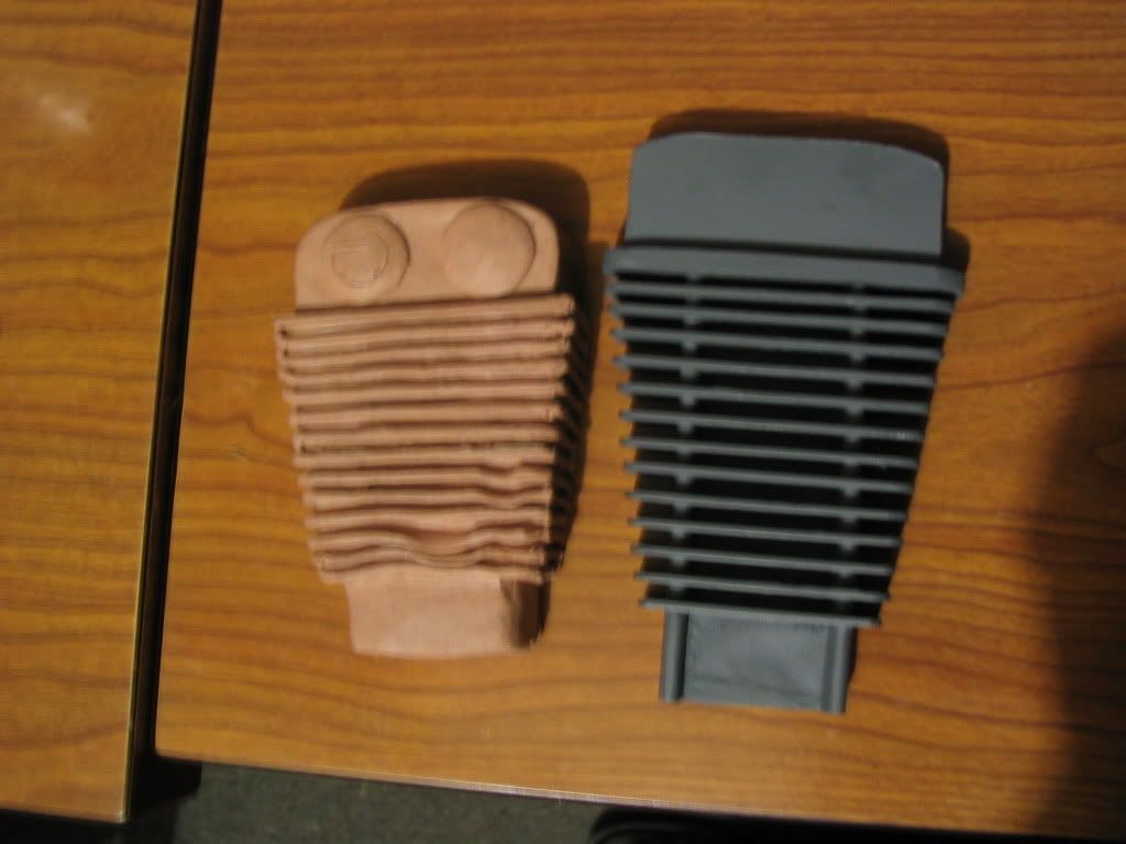
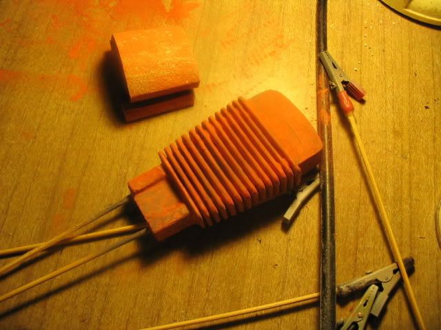
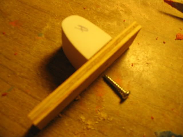
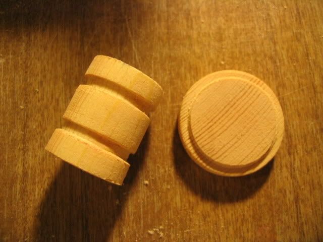
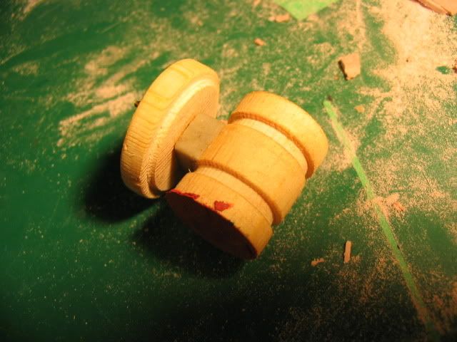
The smaller detailed parts were spun out of scrap wood that I found lying about. From left to right: Light-tube 'hat', pommel, S-Block button.
My parents love collecting old wood from neighbours. It has certainly paid off! Some parts were not as tall as they should have been – something that I realised only after turning. As the image that I relied on was set at an angle, I had not at all taken that into account – hence, the grey putty corrections.
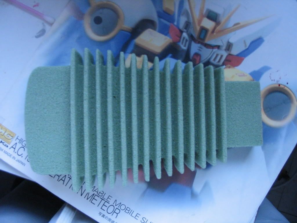
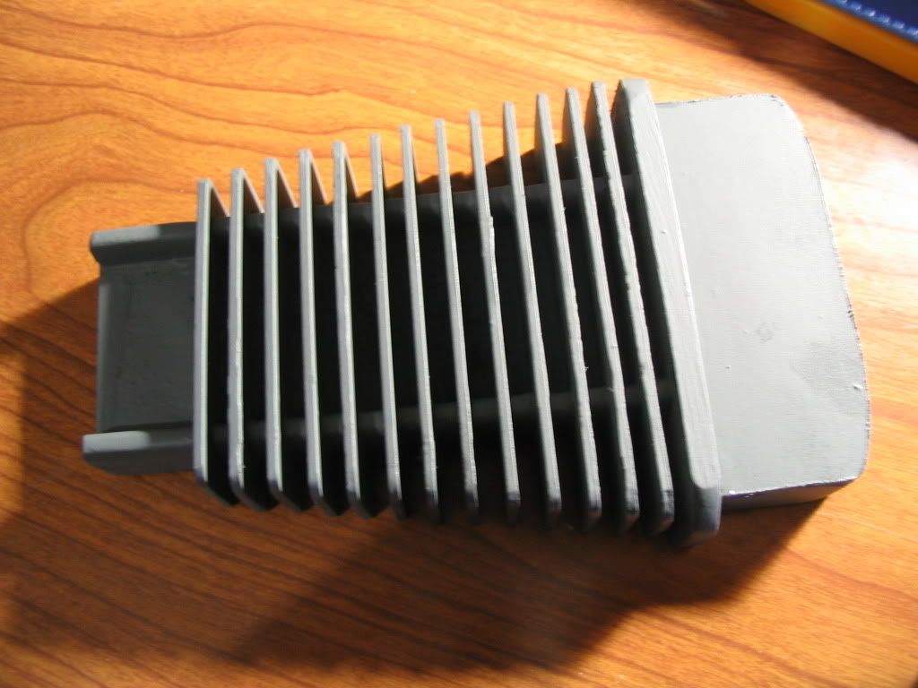
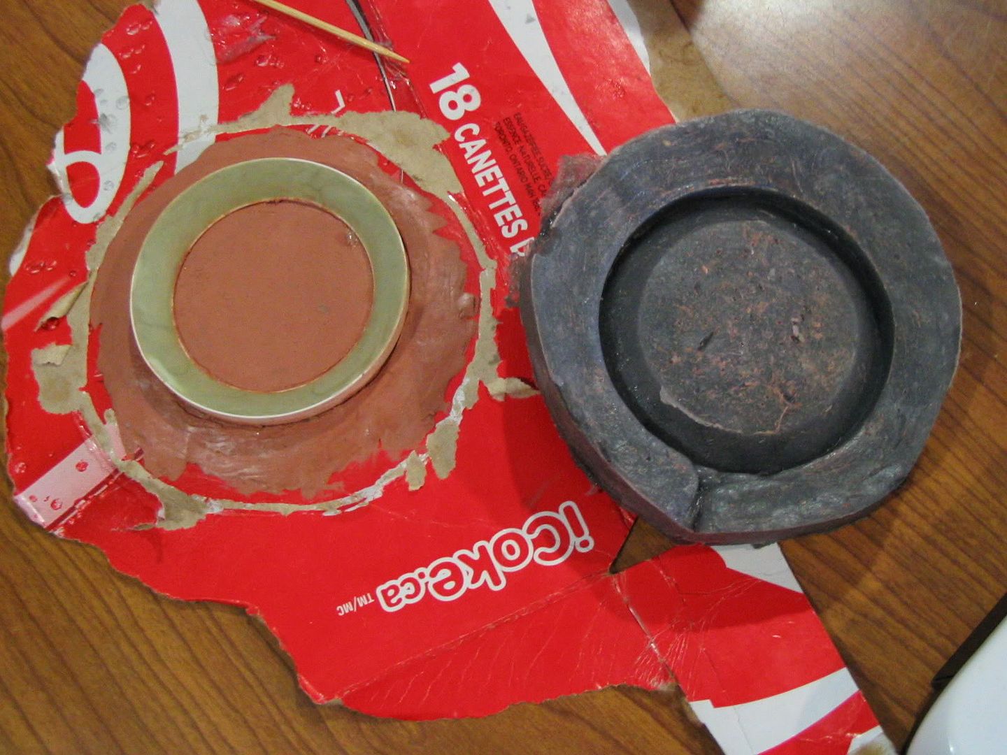
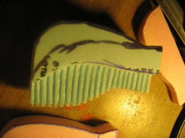
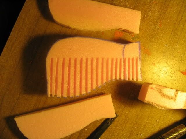
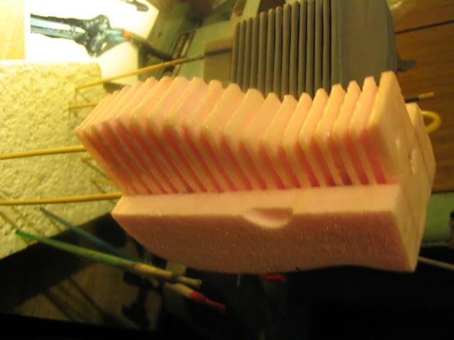
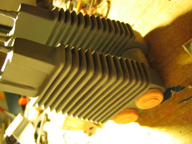
After much indulgence in thought-experiments, I decided to make the engine out of foam in order to save time. I spent three days on the above attempt. In the end, I scrapped it because of its intrinsic fragility. The florist foam could not possibly stand any abuse in the final location on the prop. After some more reading and researching, I decided to try my hand at blue insulation foam.
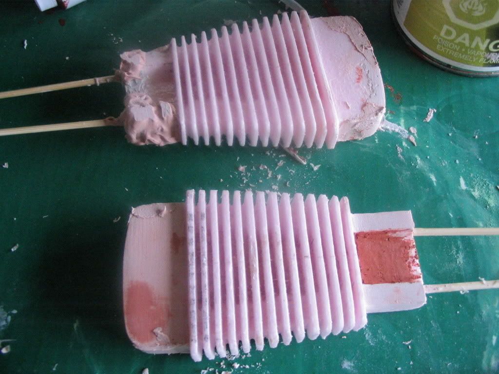
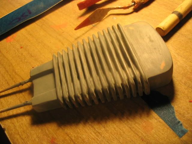
The
second foam was extremely difficult to work with. I had no hot-wire
cutter, and I was not going to bother making one. It took about six
attempts to make two acceptable (but not perfect) engines. The foam
was difficult to work with because it balled up and came apart in
chunks. Its tenacity and cohesive properties made it unlike anything
that I had ever dealt with as a model-builder. I finally learned that
using a file and sandpaper were my best tools (and a scroll saw) in
dealing with this material. If I worked with this item more in the
future, I would definitely consider making a wire-cutter.
|
|
|
|
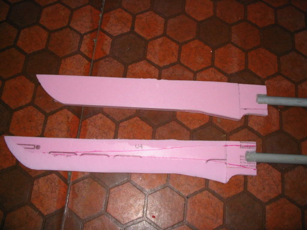
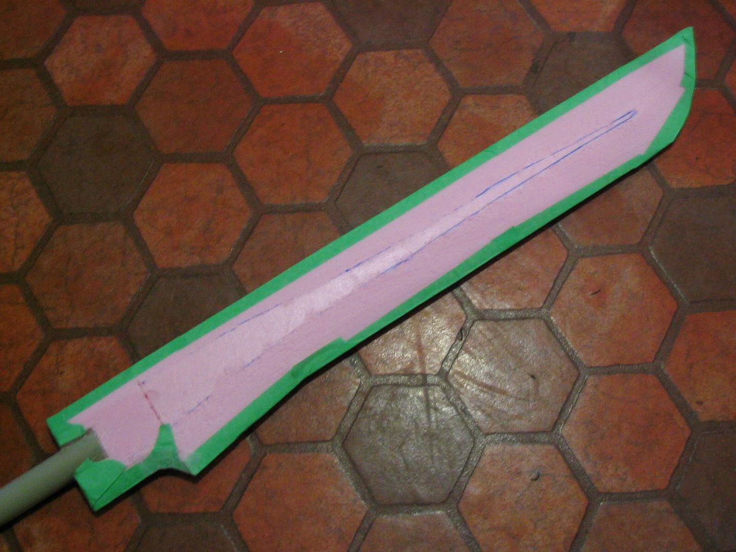
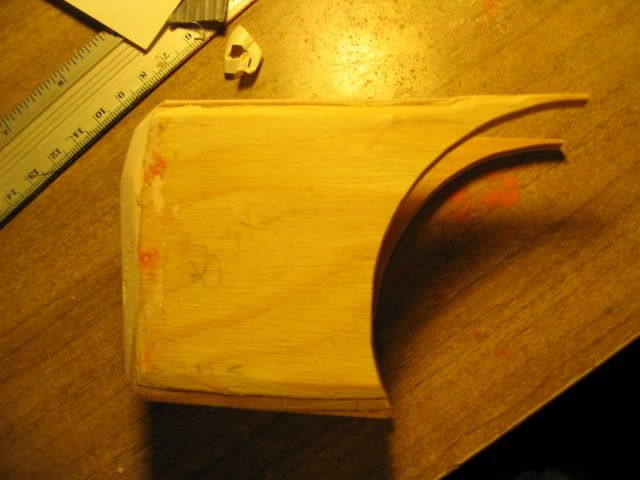
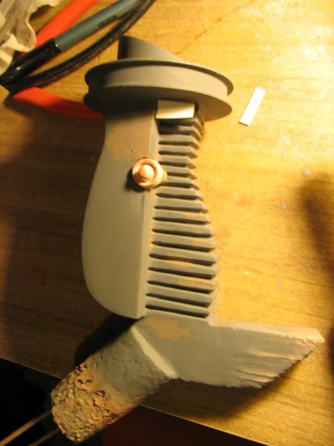
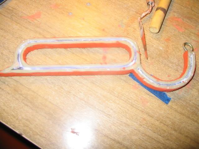
Some time last summer, I did get to work on the blade. I cut a rough shape out of a scrap plank of wood and hacked the edge down with a butcher's clever. I then bevelled it and levelled it with rasps and sandpaper. I coated it in many layers of airbrushed varnish – but in the end, this was a wasted effort. You can see some of the Bondo patching that I did in various areas to make it just that organic leaf-like shape that gives it its beauty. The shape of the sword is an aspect of this project that I really enjoy.
To attach to a handle, I knew that I needed strength. This piece is not plywood, so I needed to take into account of its cross-sectional weakness. Such that a threaded rod was used to anchor this to the would-be handle. A deep hole was drilled into the wood, about 20 cm. The rod was placed into the end of a drill and spun into the 1/4 inch hole made just so. Epoxy glue was previously forced into the deep hole with a piece of wire. Curiously, when the rod reached the end of the hole, the epoxy cracked and seeped out of the side of the sword. Very surprising!
What is that white thing? It is a doo-dad that I found around the house. It is a copper and plastic coupler that happened to fit inside the ¾ inch PVC pipe (with lots of sanding and filing, mind you). I cut a slot into the sword and the copper end was inserted. It was bevelled into a roughly hole-like form with the assistance of my rotary-tool. It was epoxied, and the rod was then spun-through with a nut on either end to stabilize it. Genius, isn't it?
April 30, 2010
|
|
|
|
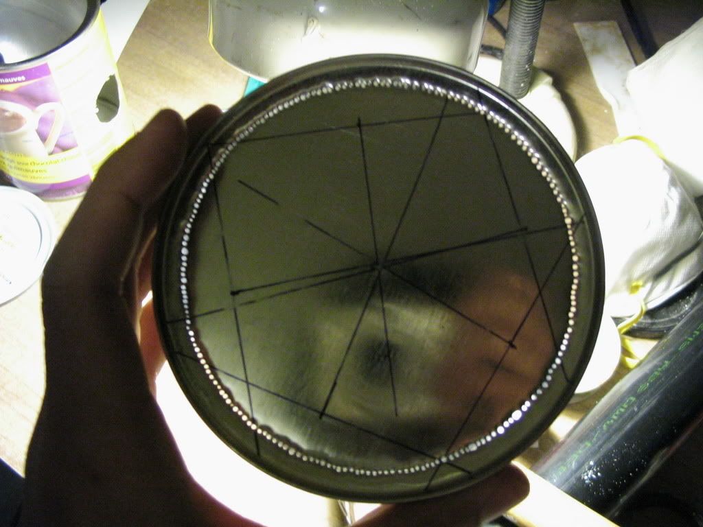
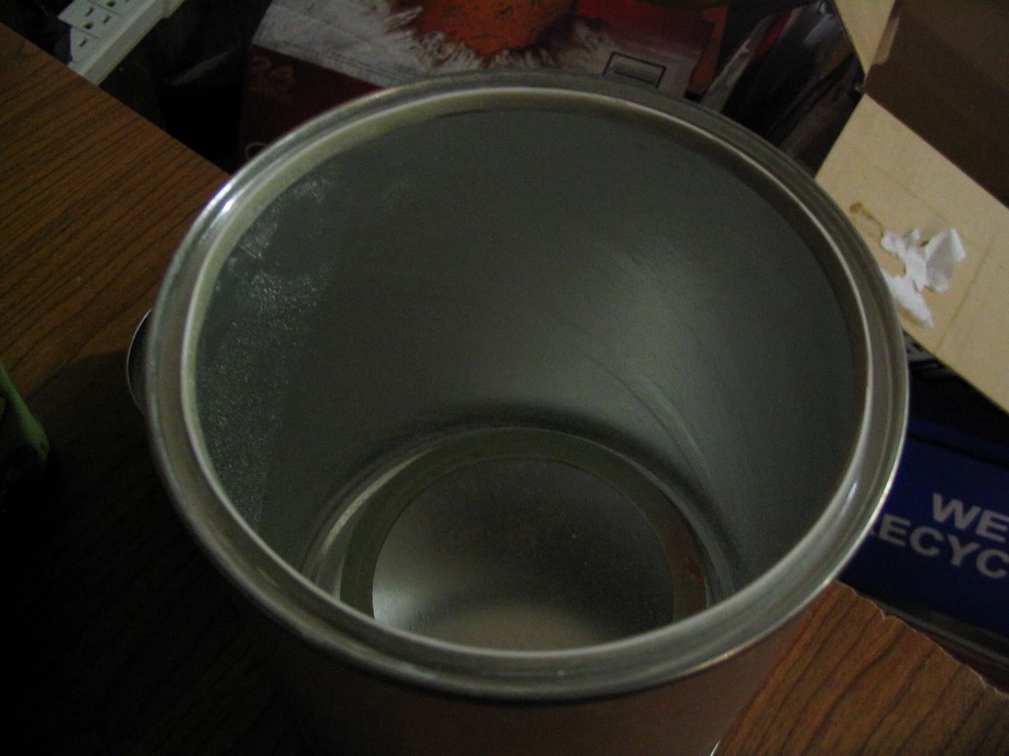
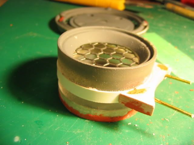
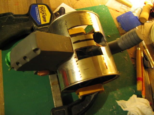
This sword was nothing but trouble! I could not 'get away' with slacking on any part of the design. It was determined that a paint can (1 quart?) would offer the perfect shape to make the main drum with. However, both ends needed a 'lip'. Such that the bottom needed to be cut out. But how would I make a perfect cut? I googled some old geometry and re-learned that any two perpendicular bisectors would lead me to the centre of the can. But, of course, since the lip was raised and I had difficulty determining the exact location. A compass was then spun around and I used a nail and hammer to slowly punch around to cut out the bottom.
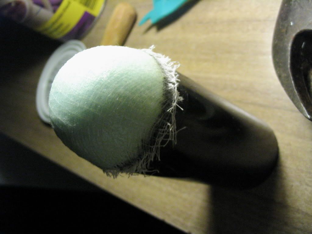
This funny phallic shape is to be the chamber. I don't know how wide it is, but it is something about 3 inches. I'd say about 5 cm in diameter for those of us who are metric. I covered the end with a foam 'cork' sanded into a dome shape. Epoxy glue and cheese cloth were draped over it to give it some strength against coming damage. I wanted to over-build this as much as possible.
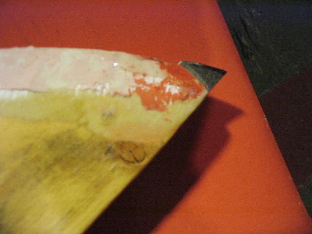
Speaking
of over-building, I knew that I'd be constantly repairing the tip
from damage. Such that I cut a slot and wedged a piece of steel sheet
into the tip. I cut it down with my rotary tool and shaped it
accordingly. This will greatly improve the longevity of my prop at
the convention.
|
|
|
|
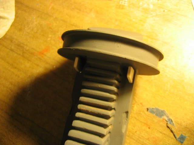
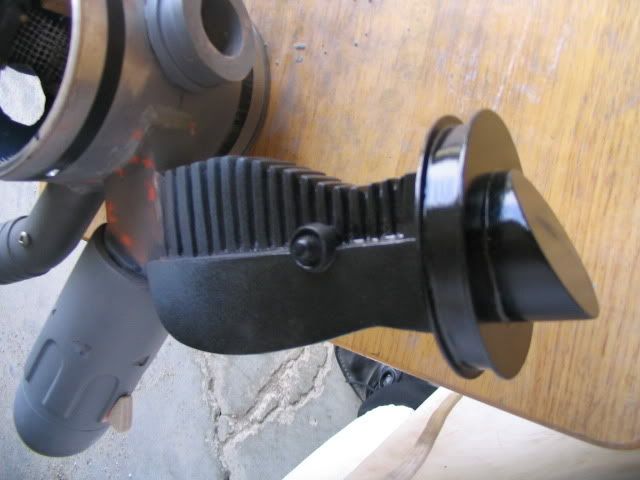
The base is removed and it needs a dire amount of grinding down.
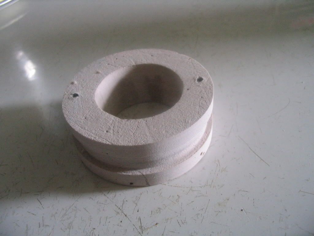
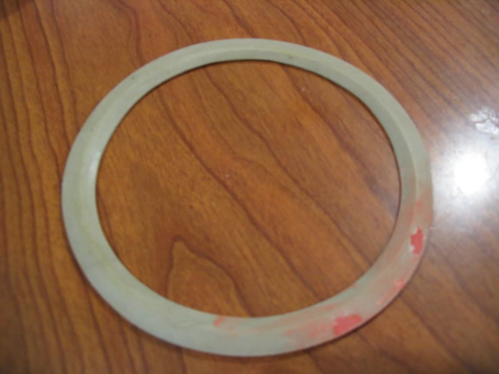
The middle part is the hand-stop that rests atop the drum. A doughnut / washer was made out of two concentric rings of bristol-board, taped onto a flat board, this was the disposable mold in which the medium would be cast in. In this case, thinned Bondo was poured in and allowed to cure overnight to get a basic shape. As you can see from the two holes atop, it was mounted onto my 'lathe' and spun into a proper shape. Many imperfections existed, but it was soon to be taken care of with many coats of thinned Bondo Spot Putty and sanding.
Author's Note: Auto-Body Putty and Bondo Spot Putty are entirely different creatures.
What I call Bondo is the Auto-Body putty, which is polyester (“fiberglassing”) resin cut with a filler. It is two-part and cures in about 10 minutes into a workable product. It smells very badly and is highly toxic. It is used to fabricate large forms and was meant for filling holes and dents in vehicles. It comes in metal cans and a plastic tube of tinted catalyst.
The Spot Putty is a dark-red filler cut with Lacquer thinner or something similar. It goes on and cures in about 15 minutes with reasonable coats. It is very soft, very crumbly (thus dusty) in finish. It is meant for fixing small dents, dings, scratches and pin-holes.
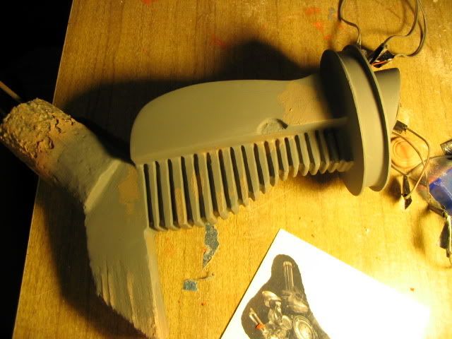
The spun wood part here has been repeatedly primed. One will form a strange L protrusion (“L-Arm”) that comes out of the main drum, and the other portion will be a light-up tube.
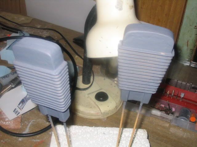
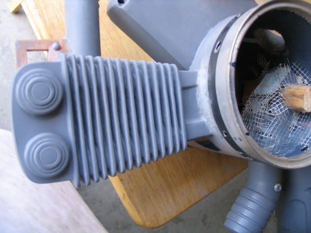
The engines, carved out of foam. But many layers of Varathane (water-based sealant) was piled on top to protect it from coming paint. If you intend to prime and paint your foam, sealant is needed. Some use gesso, some use white glue. Ultimately, it was uneccessary for me, as I decided for the sake of ease and toxicity to 'paint' a thick layer of mixed two-part epoxy glue onto the raw foam parts (as with all of my foam parts for this prop). Polyester resin requires sealant, but epoxy does not dissolve polystyrene foam.
Unfortunately, these things were far from perfect and called for much modification. Here you see globs of Bondo and red Spot Putty in order to equalize the two sides. Very rough, very horrible work; I was covered in dust for a month.
|
|
|
|
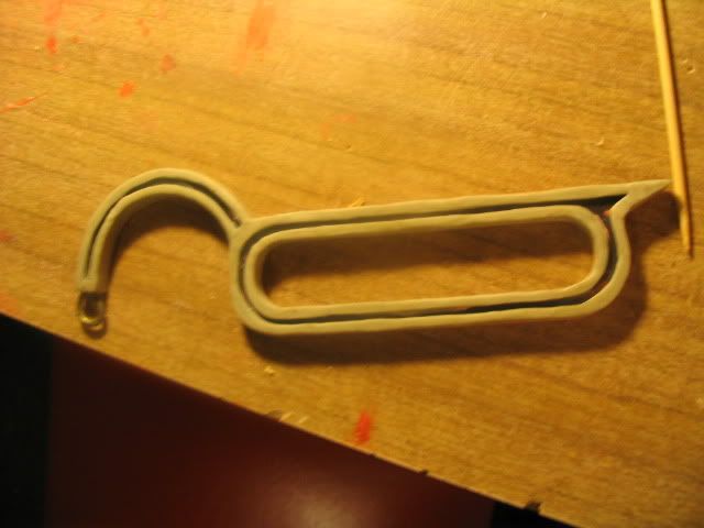
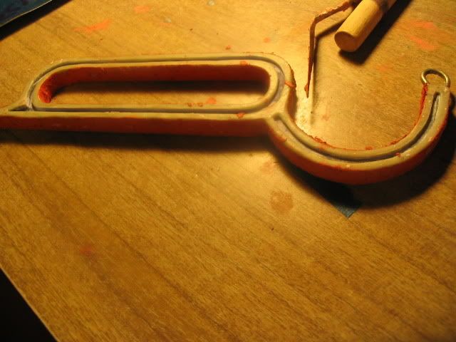
The
chamber is now being formed. This was no easy process and it took me
some weeks to figure out how to come about making the shape. It took
a while, but six (in retrospect it should have been 8) evenly spaced
pieces of modelling clay were formed into elongated D's and were
stuck in equal spaces about the circumference of the black PVC pipe.
Thinned Bondo (Bondo + Lacquer Thinner) was then slathered on.
[Please wear a respirator mask!] It was rasped and sanded down to be
as even as possible until I revealed the clay. I then used tools and
I pulled it out to reveal the recesses.
In the end, my chamber was then rounded off with my rotary tool (their recesses) but it was then discovered that the overall shape was far too long! Thus I cut out and re-attached the head with glue and metal pins.
Interlude: More from last year.
|
|
|
|
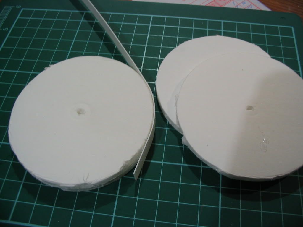
The first part is the only section that I'd end up re-using. These are discs cut out of paper-backed foam from the dollar store. Two of them high and then wrapped with a thin ribbon of plastic card. They would then be held on either side by a larger disc of hard and thin plastic sheet. (Think of an Oreo cookie). It will form the 'hat' of the what I call the 'S-Block'.
The middle part is honestly very good, and it took about a day to do this last year. The plastic rod that was used to wrap about the pipe was a genuine bitch to hold into place, even with the assistance of drilling and pinning. But after I glued it in, I could not remove it. But it was too big to fit properly with this year's prop, anyway.
I made two foam forms for the sword last year, but when I started to cover them in fiberglass (polyester resin) the masking tape that I used to seal the foam started to peel off and the blade was ruined.
|
|
|
|
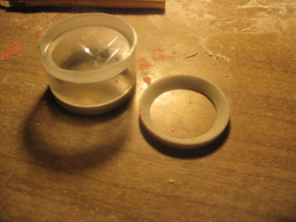
The ring for the smaller drums were made out of epoxy putty and plastic card. The dark purple object to its right is a silicon caulking mold (mixed with paint and glycerin to speed cure) that was made to duplicate this object. The smaller drums at the time were small tuna cans.
The arms that hold them there are rolled epoxy putty, being roughly formed in the middle image. The same method was to be used on this year's brackets.
The far right image is of an old engine that I had made out of clay, and the one made of plastic and foam. The clay engine was ruined when I tried to duplicate it with a plaster of Paris mold. More unfortunately, the good engine was to be ruined by the thinned caulking (specifically the lacquer thinner in the silicone mix) mold making process... That's when I gave up.
-_-,,
|
|
|
|
The above left shows a ring that I made by hand to the best of my ability. (I had not made a lathe back then) It was meant to sit inside the inner lip of the can to give it that raised detail. It was going to be molded for duplicates. The middle shows the very large (oversized) can that I used for the main drum last year. I manually glued a thin ridge of plastic card there with difficulty. The whole thing was a headache, and I'm glad that I failed.The last is the chamber from 2009. I was going to make it entirely out of foam. Not a bad looking thing – but when I covered it in weave and fiberglass resin, it was beyond repair as the details turned to mush beneath the heavy burden of the resin.
May 12, 2010
|
|
|
|
The
middle of the lid (both of them) needed to be similarly punched out.
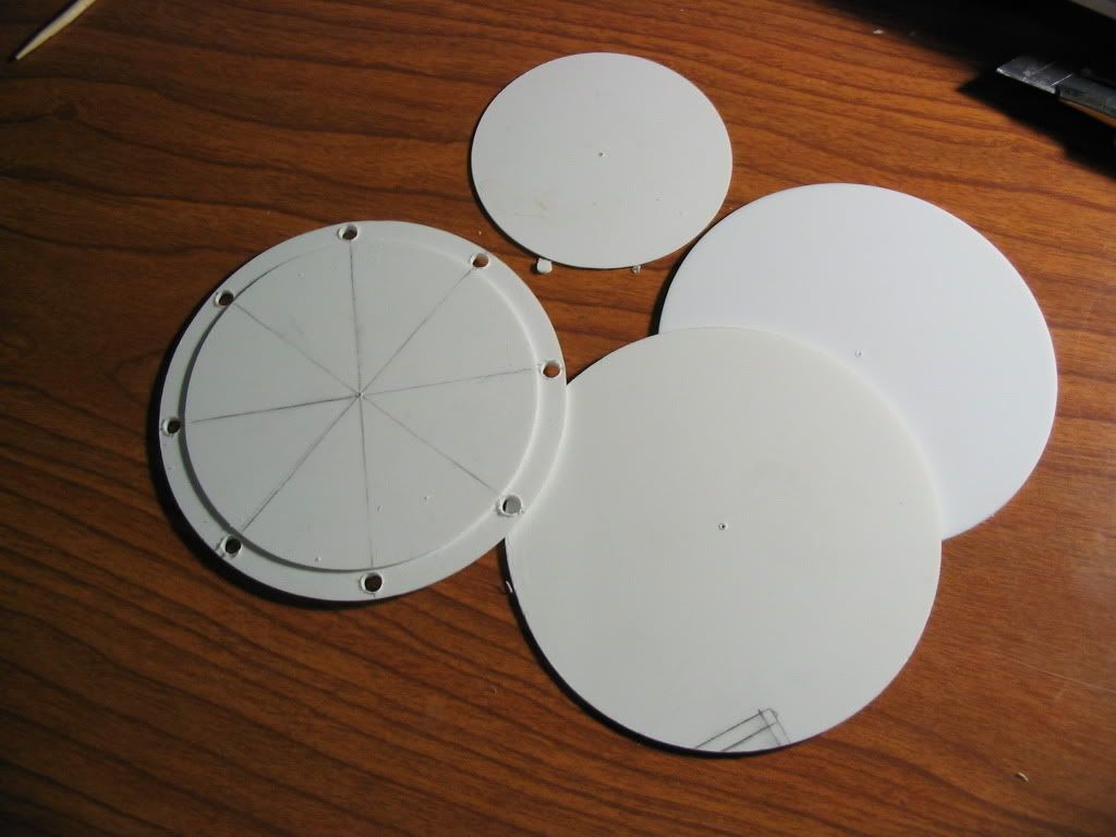
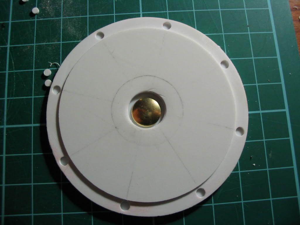
Another face plate was made in the same manner as the one from 2008/9. Two plastic discs, a recessed head of a thumb-tack and four holes. Around the perimeter rests eight recessed rivets that were punched into the thick plastic card. The four holes were then shaped to be bevelled into the centre.
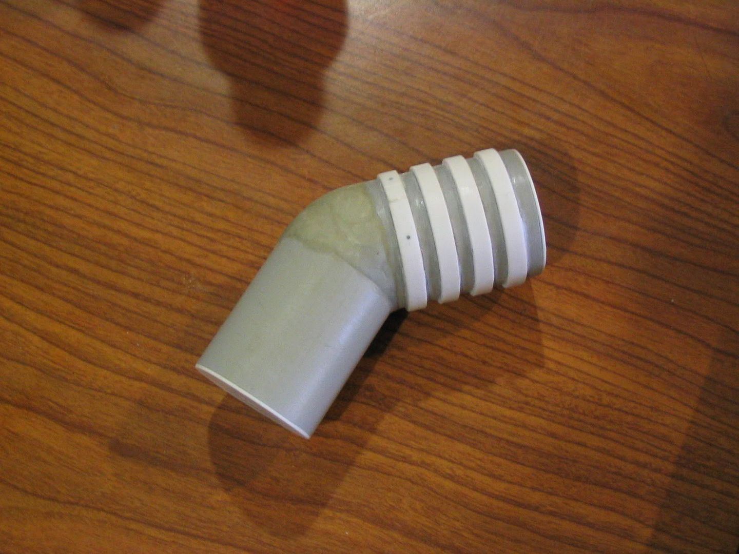
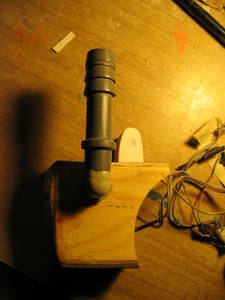
The wooden part on the far right was then spun and removed from the light-tube and attached to a section of PVC, and it was then blended with epoxy putty in order to form a neck. This part was very rough and took quite a bit of filling to look right! I regret making the angle too slight much later on. Please use about a 45-degree angle! Or save this part for last and adjust accordingly!
|
|
|
|
I
had a bitch of a time figuring out what to do for the light tube.
For months I wandered around dollar stores and the like for a pen or
something of good thickness that was clear and hollow plastic.
Finally, I found something that I had kept around for years but
hesitated to use because of its thicker outer diameter. It was a
container that came in a set of dollar store glitters. Its outer D
was dangerously close to the light-tube, but it was unavoidable and I
had to make some dangerously close shaves to the inside of the tube
as well as the hat. I actually punched through the latter a few
times, but a bit of patching fixed that and you can't even notice it
on the final prop. I was always worried about strength, and I built
it well as best as I could have.
The light-tube and the 'hat' that goes on top of it. The end of it was roughed up and a bolt was embedded into it, so that the hat would be able to glued onto it and remain strong. The bottom was going to be slotted into the hollowed out-light tube with the screw threads providing torsional strength and grip for the epoxy putty. The grey section there was separated from the L-Arm above, if you recall.
|
|
|
|
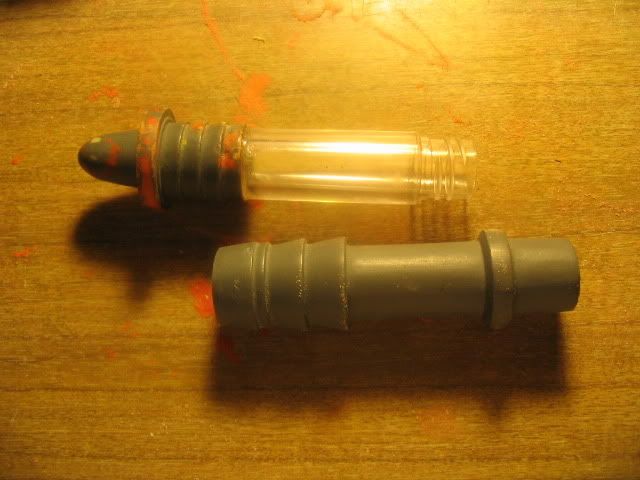
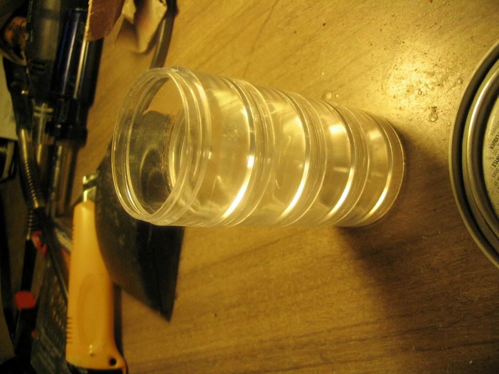
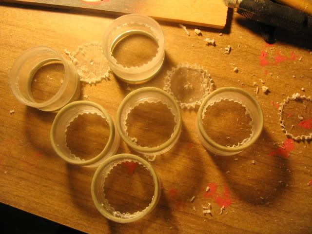
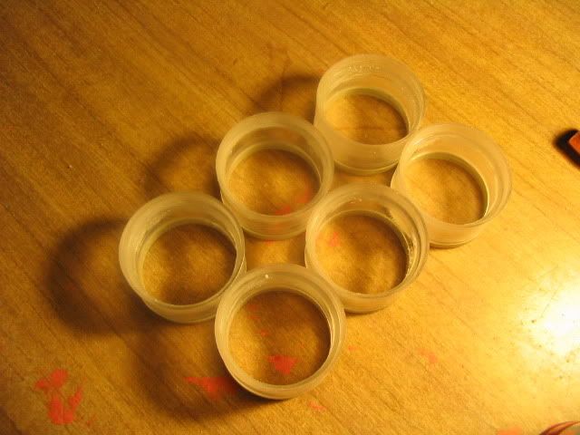
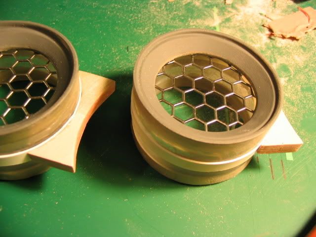
These are the items that were turned into the smaller drums. They are stacking containers meant for crafts found at the dollar store. I was coming up with all kinds of solutions to make these, from rolling plastic and paper to using the sides of energy drink cans... And then this dawned on me. There was a problem though, the bottoms of the 'cans' were recessed and needed to be drilled out and removed. Also, there was a screw thread in each and every one of them. The above images show me processing the suckers; removing their bottoms and filling in the screw-threads.
|
|
|
|
Yet
thankfully because of the recessed bottom, it allowed me to make this
ring of epoxy putty rather easily. Four holes were pre-drilled along
the circumference that allowed me to poke the ring back out of the
container after it was semi-cured (thus rubbery). This ring would
then be duplicated six times (actually more than that..)
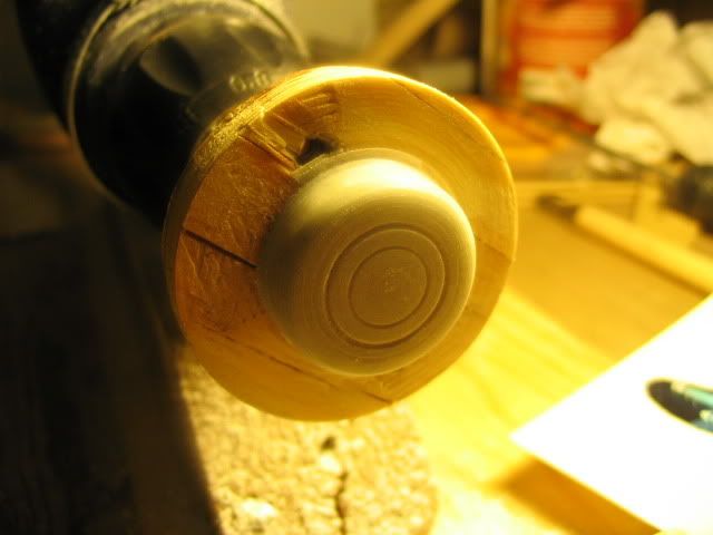
The
button that was going to be facing the engines was spun out of a wad
of rolled Apoxie Sculp (epoxy putty).
|
|
|
As I touched on before, the 'hat' for the S-Block from last year. It was refined with putty and sanding, then topped up with a section of black PVC pipe cut at a sharp angle. It was then covered with a plastic sheet, glued into place. You can see here all of the putty that I used to fill the gaps and imperfections.
|
|
|
|
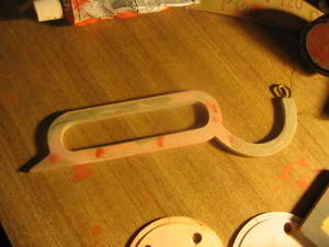
A
coathanger was the armature for the lever. Epoxy putty and Bondo
bulked around this and was sanded and filled to be as perfect as
possible. (to 0.1 mm).The refined lever with lots of sanding and filling. Constant checking with the digital caliper was used to ensure accuracy.
|
|
|
|
After
sanding, it was found that the chamber was too long. The left image
shows a chunk being cut out of it for this reason.
The middle image shows pins being aligned for gluing, as this part will come under strain when the lever is moved.
|
|
|
This is the.. 'box'. ^_^ Thin plywood cut to shape.
The last image shows the outer ring of the lid, two face plates (primed) and the 'L' Arm.
|
|
|
|
The hand-guard is being worked on. Please recall that it was spun out of a ring of Bondo on the lathe.
The beginning of the mold making process; embedding the parts into clay. In reference to the right-most image are the following parts: S-Block Button, Small Drum Mounting Bracket, Engine Button, Small Drum Lip.
Caulking will then be laid on top carefully with a gun (clear type, 100% silicone recommended!). Caulking is not the best mold making material, but it is flexible, and it is very cheap. After being pumped out of the gun, it was carefully brushed on to ensure that the details are best captured. I didn't have time to manually pat it into the shape by hand as I had too much to do -- but I recommend that you do that. Please don't forget the mold-release, which was simple vegetable oil brushed onto the clayed part. Multiple layers were laid atop each other until a desired thickness of about 5-7 mm was reached. It was sprayed with water out of a pump-type bottle to aid in the curing proccess. (The caulking is an RTV rubber that relies on atmospheric moisture to cure) When the caulking is cured (it no longer smells as vinegar at this point), the rubbery mold was separated from the part, and more oil was brushed into the recess. This was used as a tool to duplicate these simple parts.
I'd recommend using professional RTV or something better than caulking, but 'meh'; I didn't have a choice.
|
|
|
|
The
engines were primed after many many setbacks. Such as this one day
when the wind was high and it picked up my weighted foam block (the
white thing in which the engines are stabbed into) and threw it
across the parking lot! I was pissed, as it required much repairing.
The first image shows red dust all over the engine. The dust is a result of the red Spot Putty being sanded away and re-filled again and again.
The second image shows what the engine looks like after hand-brushing automotive primer onto the form and then sanding.
Image three shows the engines ready to be primed. The engines themselves easily took a month to get to this level of finish.
|
|
|
|
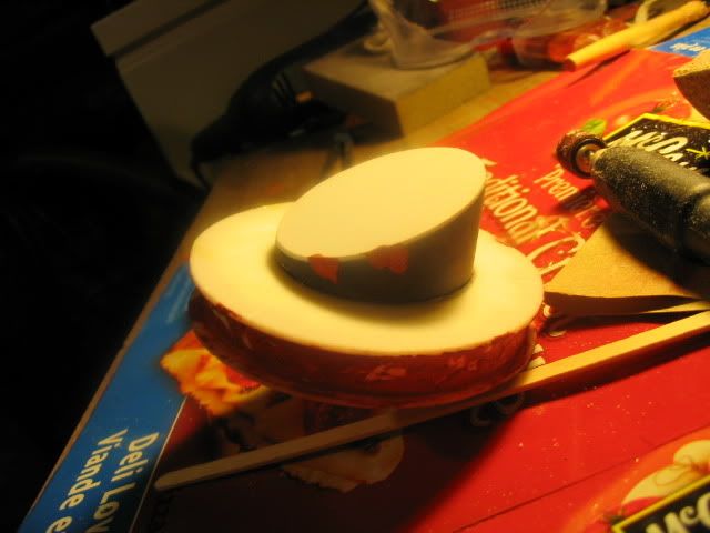
What I call the S-Block started off as a single piece of foam. After some sculpting, it was determined that it was too difficult to arrive at the needed form. It was scrapped as a result.
The middle image shows a sandwiching approach to sculpting this form. Although imperfect, it was far more satisfactory. I was worried at this point in time as I was a week behind my projected progress.
The S-Block now glued together. The beginning of the indents are added in with a sanding drum attached to my rotary tool. These indents will be for the 'buttons' to be added far later.
|
|
|
|
A tail is added to the lever, pinned into place to ensure that it stays on.
A noodle of epoxy putty adorns both sides now, to give the raised edge.
The third image shows the filling of imperfections.
May 21, 2010
|
|
|
|
The
drum is now marked for cutting with a rotary tool.
The box has an outer bevel made out of thinned Bondo – this ended up being a mistake, as the Bondo was soft and stayed that way over a week after I thought that I had cured. It separated and cracked repeatedly!
The hole is marked into the box, and the excess is cut off and removed in anticipation for the tube and wiring...
|
|
|
|
The tube itself is filled with water and blue food colouring. It was plugged with hot glue and clear silicone caulking. It was sanded from 200 > 2000 grit paper and clear coated repeatedly.
Middle images shows the lighting mechanism - - the same one that SHORTED a week before the convention. (>.>) The tube is now attached to the box, and the wiring runs through, but there is no room for the battery box! It will have to be moved into the main drum.
|
|
|
|
Using
a cutting disc, a rough hole is cut in the paint can for all of the
parts.
Bondo (pink) is used to cast into the mold made of silicon caulking (milky-white). A total of seven are made, but only six are needed.
The last image shows the cast rings at work, but some of them turned out to be horribly flawed, causing me to make two more originals out of epoxy putty and turning them on a lathe. Perhaps I should have done this from the start?
|
|
|
|
The eyes are epoxied onto the engine after casting and clean up. It's very handsome at the moment, isn't it? It reminds me of some robot from a Pixar movie...
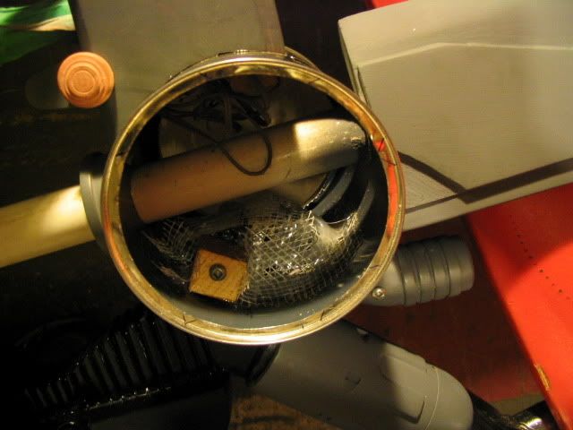
The two halves are then sandwiched together. Two pipes filled with insulation foam (shoved inside of them!) gives the hollow tubes strength, while a metal wire runs through the foam and into both engines. This serves as the metal pin that gives much more strength than a simple surface bond – especially since I know these engines are but a thin coat of epoxy glue around a foam core. Note that both sides of both engines are lovingly detailed.
The last image shows the new exhaust pipe that comes out of the engine, blocked at one end with hot melt glue. It is wedged into place and held there by epoxy putty and epoxy glue. A lip of epoxy putty is added onto the edge of the pipe, and red Spot Putty (Bondo brand) was used to fill in the gaps.
|
|
|
|
The chamber after many coats of filler and refining work. The additional recesses were cut out with the help of a rotary tool, but it was far from a clean job.
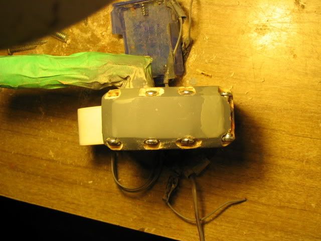
The middle image shows the top of the electronics box. This bit of detail is made by wrapping plastic sheet about a foam inner. The screw goes in from under to hold it there, firmly in place. Again, it never hurts to over-build and anticipate problems.
The S-Block undergoing more work. You can see additional putty marks here, and it is being glued (it was also pinned with bamboo BBQ skewers) into this 'arm'. The beam goes into the paint can, and the round end sticks into the hollow of the chamber.
Aren't
I clever?! Yes, yes I am.
|
|
|
|
Additional details such as the fins under the 'hat' are then added. They are made of plastic card and are pinned and epoxied into place. Please don't forget this on YOUR prop!
The
button was turned out of wood, and a mold was made from the master
and two copies were used after sanding and refining on the final
engine. They are held in place by the recess, but are also backed up
by shaped epoxy putty.
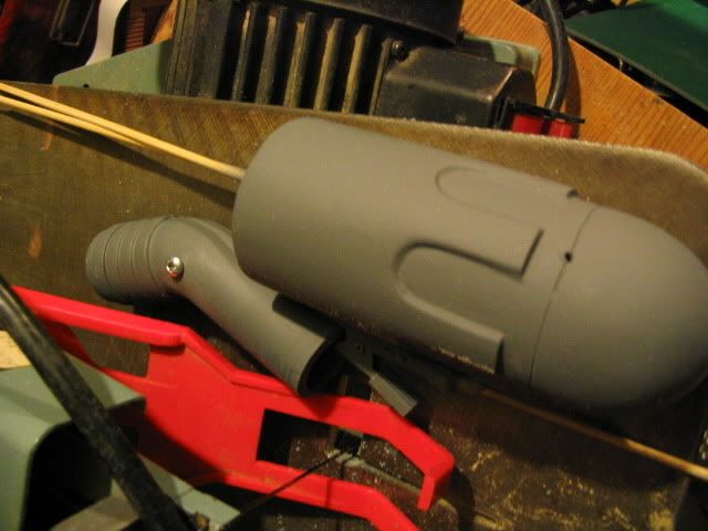
The light-tube along with the box are now ready to be installed. The tube's main connection with the box is backed with an L shaped piece of wire – I wanted to ensure that this weak joint would not SNAP at the convention. However, I should have reinforced the light-grey Apoxie Putty as well as it was the part that broke ....
|
|
|
|
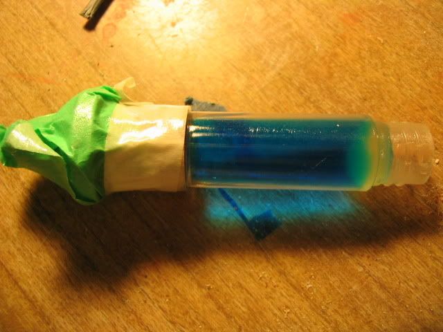
I needed to show you the lighting mechanism. It was going to be ultra cool, and it would have made me pimpin' at the convention, but alas! The circuit shorted when I installed the blue tube in the middle. I guess that the LEDs must have touched each other, as the IC seemed fine from my voltimeter testing.
The blue tube is from an emptied plastic bottle of glitter. After washing, it was filled with water and blue food colouring. The other end was plugged up with a glob of hot-melt glue and then finally sealed with clear silicone caulking. I wanted to be double sure that it was not going to leak. The top was installed by gluing a nut head-down onto it with epoxy, and drilling a receiving hole into the 'hat'. The light tube is also hollow at the bottom to receive this blue tube.
The circuit itself is from a dollar-store lamp that pulsates and rotates between three colours in various combinations. I intend to fix this fault for the next anime-con. I will be sure to update this page again when the time comes.
The last image shows the chamber and the L-arm ready and waiting to be installed.
May 23, 2010
Ahhh --- so much to do, so little coitus!
|
|
|
|
So little time indeed!
The
first image shows the lever undergoing much work. Ideally, I should
have used plastic card to produce the raised edge, but I couldn't
justify 'wasting' an entire two sheets of styrene to do this. In the
end, the Dremel had to be used to grind out and refine the channel.
Multiple layers of red Bondo Spot Putty had to be added, as well as a
few more types of filler as well.
The middle image shows one of the doo-dads that goes onto the end of the box. There will be an epoxy neck that goes in between these two forms, turned out of wood, and a fin that will be pinned onto the very end of it.
The last image shows the box with the screws attached. As you can see, the recessed holes are still incredibly messy at this point in time. You can also see some of the patching needed to deal with the constant warping and cracking on the end of this item.
|
|
|
|
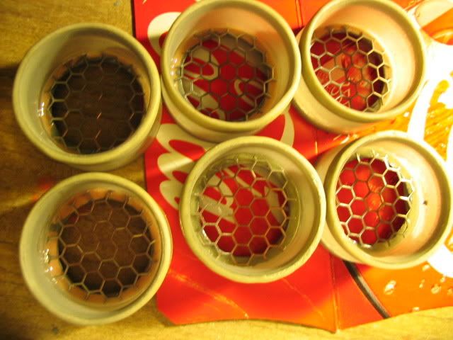
For accuracy, hexagonal modding mesh was procured long ago from the Internets; it was meant for computer modding. It had to be washed with detergent to remove the oils involved, and it also needs to be painted as it would rust when exposed to the elements. I also needed to wash all of my reproduced parts, as all of them had residual oils from the casting process.
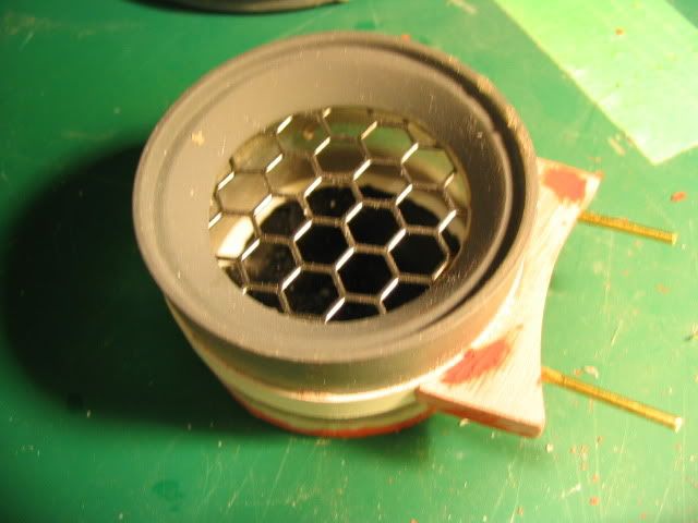
The lips of the smaller drums were installed with CA glue (cyanoacrylate / “super” / “instant”) with the help of a hobby nozzle on the end of the bottle. Turning the hollowed canister upside down, the modding mesh was cut into a rough circle of the approximate size using a round piece of masking tape as a template. It was then epoxied and then further hot-glued into place.
Following, the brackets; cast from thinned Bondo pulled from caulking molds, were installed with CA.
Finally, 1/16 brass wire was drilled and glued into place to allow the bond to be strong. There will have to be mating holes in the large paint can. These I have no photos of, but I used label maker tape to allow my drill bit to grip onto the slippery steel can during drilling. The holes in the large drum were made much larger than 1/16th but had to be widened even more (laterally) with a bit to allow for human error when installing the smaller drums.
|
|
|
|
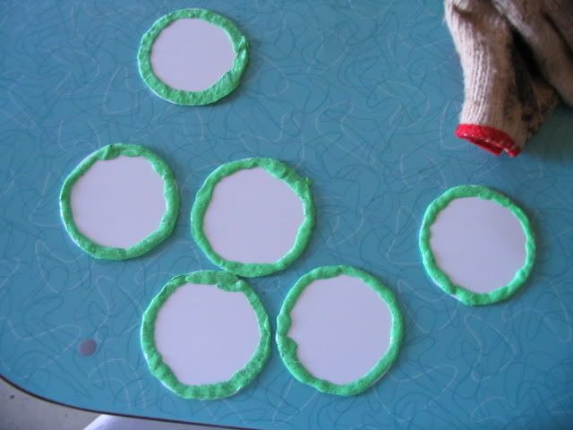
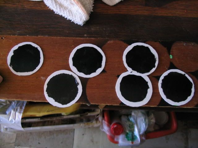
Six circles of styrene were cut out from stock sheet and masked off with Silly Putty.
The centers were sprayed with black paint and then their masks removed. The exposed perimeter would offer a sure grip to the inside of the smaller drums. The black paint will offer the illusion of depth, as it will be difficult to paint the underside of the bottom during spraying. This ensures that they are well darkened before hand.
The right most image shows the brass rod now attached, but also offers what the small drum looks like in raw. A plastic ribbon of styrene was wound around it before installing the copied bracket; the lip is installed, primed, filled and sanded; the brass rods go through every part to provide a strong anchor for the otherwise fragile bond; and finally, the styrene bottom is glued into place, and a liberal amount of Spot Putty is applied as filler to the seam.
Three external rivets would then be placed evenly around the ribbon for final detailing. Please remember this!
|
|
|
|
The neck of this detail is now installed. This will go on the end of the Box. It reminds me of the bridge of a Corellian Corvette from Star Wars – but you don't know what that is. There is also a 'screw' detail on the end of this piece of wood. It was two circles (one for either end) cut out of styrene. A ribbon of masking tape was draped across the middle and this was used as a guide for removal of material. With the middle of the circle missing, the two hemispheres of plastic (on either side) would be glued onto the hammer-head end of this detail part to replicate the look of an embedded screw. Again – attention to detail, folks!
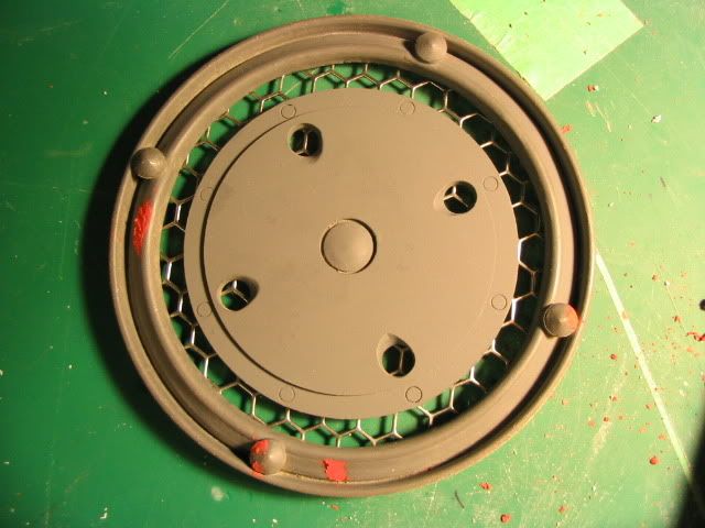
The face plates are being installed. The inside of the paint-can lid was removed (earlier) and mesh glued to the underside. Because mesh is oh-so-full of holes, it has little to go on as a strong bond. Such that a blob or two of epoxy putty and hot melt glue (and some scraps) offer backing to allow the mesh a good bond with the small area that is the lip of the lid as well as the plastic face-plate itself.
Accuracy is something that I pride myself in, and so: four small 'bolt heads' were made out of punched styrene sheet, topped with a hat of epoxy putty shaped to a rounded point to replicate the look of the digital art. They are held in place against the awkwardly angled inner ridge by a piece of sculpted epoxy putty. Incredibly useful stuff, it is.
Right image: more filling and sanded are needed.
|
|
|
|
Then,
for the next few days, much progress was made but few pictures were
taken as I was horribly hurried.
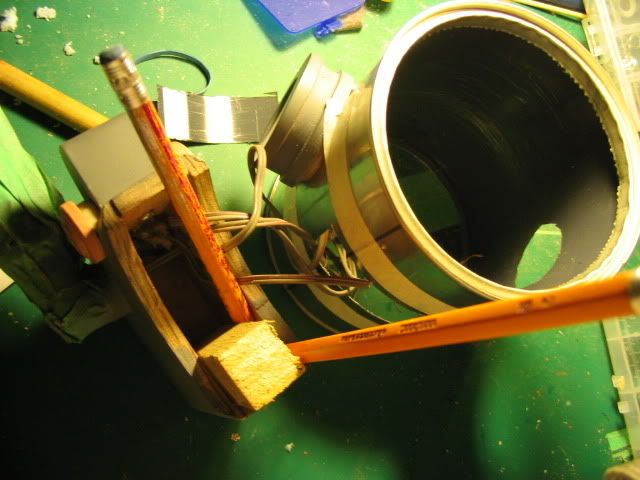
The left image shows the 'box' during mid-gluing. A small block of wood is attached there with epoxy to provide extra grip into the main paint can. Pencils act as quick wedges until the epoxy glue cures in about 10 minutes. The masking tape on the can indicates where I should cut with my rotary tool.
The middle image shows the 'box' finished off, more or less. This was a very trying process that finally met to completion many weeks after initial priming; the thinner was still evaporating and even during painting, cracking was occurring. I settled with the issue by leaving it in the hottest sun possible on a 30 degrees-Celcius day for as long as possible to do whatever damage could possibly done to the part, and repaired and refinished it. Anyway, the image shows the twin ports that allow the engines to dock into the paint drum. They engines are then screwed in from the underside and a mixture of hot glue, drywall weave and epoxy glue are used to still it.
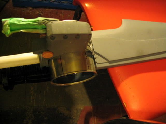
This is a test fit for the blade itself, into the large can. The L-Arm does not fit as low as I would like it to – not without compromising its parallel line with the edge of the sword. There's nothing to be done, and I don't blame myself (too much) for the inaccuracy because of the lack of images available.
More clearly seen now is the drywall weave that gives the hot glue (and epoxy) lateral strength when tried against. Peeking at you also is one of the same 'buttons' that adorns the face of the engines, now relocated to the box (I had many pulls) to replicate this bit of detail seen in a motion blur. The blade is also very much finished off with two thin pieces of wood panel adorning the sides. The basic shape was sketched out and then cut out of masking tape. This shape was transferred onto the panelling and cut out (twice) and glued onto either side. With a power sander, it was bevelled down into the blade, being more flushed at the tip. The blade itself, and all the wood on it, was repeatedly sanded and filled with Duplicolor Automotive Primer. I used this basically un-thinned, brushed it on, and sanded between coats to hide the tell-tale wood-grain. (Thank Gord Rose that it was a hot summer-like week!)
|
|
|
|
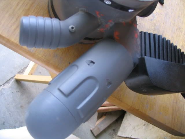
Here
are some alternative views of the Box. I should have to note that
making the recesses for the screws proved very trying, as cutting
them by hand (with a rotary tool) lead to a few too many OOPS
moments. Not to mention that the holes that I drilled were often too
small. This; along with the warping during the final curing process
as the lacquer thinner of my thinned Bondo was dissipating; lead to
many large cracks, dents and imperfections. Through trial-and-error,
I found the most success with a negative-mold technique using uncured
epoxy putty and squishing a wet pen into the mass and creating a
perfectly recessed dent for the screw head to sit into. I also
discovered (overly late) that the sanding drum is much more suited to
shaping wood than a cutting burr or drill bit could ever hope to be.
Noteworthy also is the fact that I used long metal rods to pin the smaller details onto the box. I did not want them ripping through my comparatively soft Bondo convex face.
The last image shows the best attempt I made to position the chamber along with the S-Block. You can see some patching here and there, of course. It's not perfect, but it's the best that I could do.
|
|
|
|
Perhaps
you can share some of my worldly joy as I was beginning to see my
baby come to life. Yes, this is positively my baby, after having
spent some five months on this version of
the prop alone!
Leftmost shows the black label-maker tape that I wrapped around the main drum to recreate the band seen on the images. I wanted to use plastic card, but since I had some of this about, and it was faster to use, I opted for this. I ended up supergluing the ends down, just in case they ever decided to unravel in the summer heat. Again – it never hurts to overbuild.
The S-Block has been painted gloss black previously, but it turned out that it needed to be repainted near the base anyhow. The parts aren't aligned the way I wanted them to, but .. because of the L-arm, there was nought that I could do...
The middle image shows the engine block set into place. The seam was obviously large, and I had to fill it in with the same weave that I used earlier. I then stuck a bunch of hot glue on the underside to hold it still and used Epoxy Putty to sculpt around the shape and used traditional seam-hiding methods to cover this up over the course of a day.
And wow – it starts to look like something. As for what it looks like -- “the fuck if I know!”
|
|
|
|
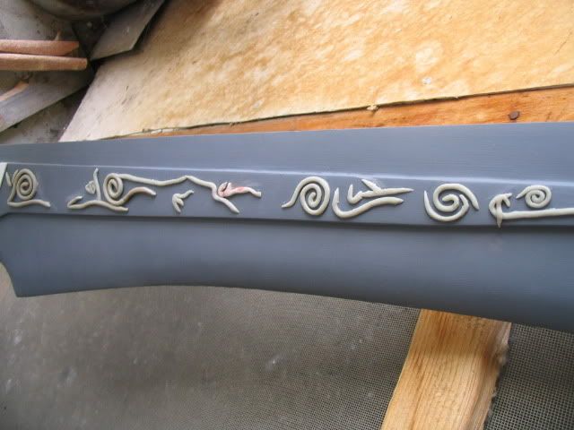
It
was crunch time and this was done two days before the convention. I
stayed up until 4 A.M. making the runes on the blade. I wanted to use
something simple, but hot glue was not an option after testing a few
passes on some paper. I had to go with epoxy putty. Rolling it was
time consuming, but the end result is satisfactory. I copied the
runes as best as I could given the images that I had. I admit that I
had to bullshit some of the runes on the other side as one side was
much too short. It's entirely my fault in that area. In my defence, I
was really too hurried to start again. The three stripes were made
out of styrene sheet, superglued right onto the primed wood. I regret
not having spent more time on the runes, and if I get a serious urge
to upgrade my sword, this will definitely be addressed.
|
|
|
This is the last day before I leave for the convention! Oh noes! Hurryhurryhurryhurry!
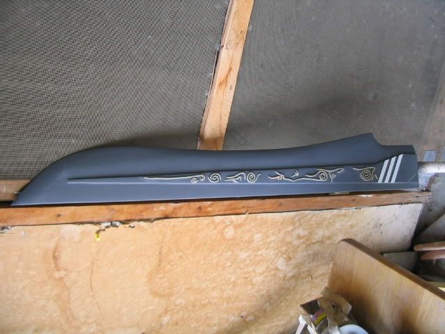
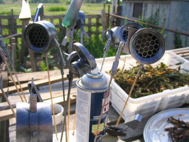
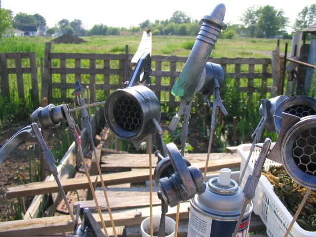
Here are some images of the painting process. After sanding and priming I was finally able to spray a nice thick layer of Gloss Black. In order to give it a realistic and un-tacky looking metallic colour, I used Aluminium (which looks suspiciously like Chrome these days..) and misted it over the parts in short and irregular bursts, leaving some of the black visible in blotches. The holders that you see are what I use for my models, they are alligator clips hot-glued onto a bamboo skewer that holds the part. They are then stuck into a block of foam during drying / curing.
The two mains are attached, being the drum & accessories and the blade. It was pinned and then glued and screwed into place. I apologize for the lack of images. I stayed up all night completing it, so please forgive my prioritizing the prop over photographs!
There it is, about two days after the convention! I had a great time. Many thought that my prop was made of metal, or that I had purchased it. I suppose that means it's a compliment? It turned many heads there – but my friend pointed out that the hilt is a bit too long relative to the sword, and the sword seems a bit too big for me. I should throw acid into his face for that, shouldn't I?
Its
received a bit of damage here and there. Most notably, the
light-tube broke when I leaned on it the wrong way during the last 30
minutes of Sunday. I spent the last ten minutes and about $10 to buy
convenience-store epoxy glue to repair it! My biggest regret was the
burnt out lighting circuit; I would have been SO PIMPIN', and the
wenches would have not laid off. But alas!
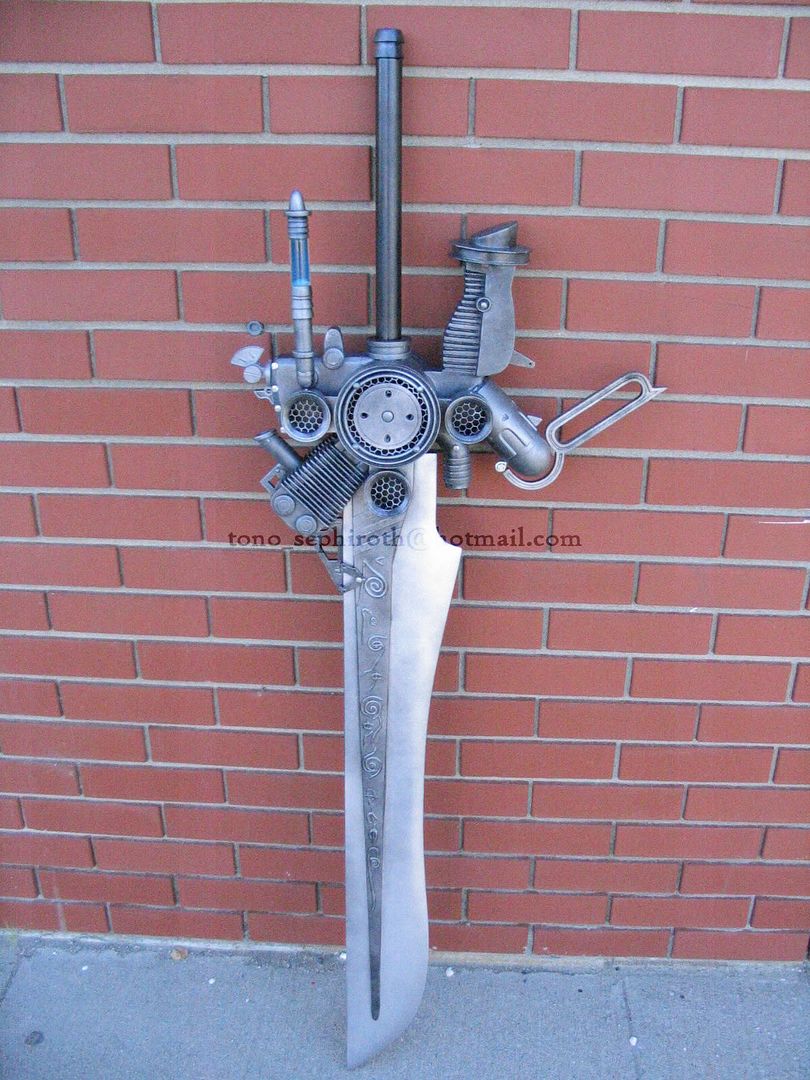
It survived quite well – especially thanks to the metal tip!
Email
/ spam / flame me at the following: (I am also open to offers of
unattached fornication by virile and healthy young women)
Landwand on DeviantArt
Amaterasu on Cosplay.com
For additional images, please visit http://s128.photobucket.com/albums/p173/tono_sephiroth/cosplay%20wip/finished/


